

How to optimize laser efficiency by rounding sharp corners.
If your workplace cuts sheet metal using a fiber laser or CNC plasma cutter, you know that time is literally money. Cutting faster means producing faster, and improving efficiency out of a shift. Most companies focus on operational improvements: reducing loading/unloading time, optimizing cut conditions, streamlining workflows, etc. But one often overlooked aspect is part design itself. This post focuses on laser cutting sheet metal, but the concept applies to any 2D material—wood, acrylic, composites—cut on CO₂ lasers, routers, or milling machines.
On a recent visit to one of our partner manufacturers, a street light pole producer, I noticed a clever design detail on one of their freshly powder-coated light poles. The baseplate for the light pole had 4 bolt slots which were seamlessly integrated into the outer cut of the baseplate. Although the design looked cool, my guess was that this design was intended to reduce laser time. Our tour guide confirmed it, though he didn’t know exactly how much time this design change had saved them. I was curious about the time saved so I knew I had to run a comparison study.
Defining the Study


Here’s the parameters I chose for my comparison study.
- Plate size used to cut the parts – 60″ x 120″
- Thickness of plate – 0.375″
- Material – A36 Hot Rolled Steel
- Dimensions of parts
- Overall – 10″ x 10″
- Slots – 0.75″ x 0.75″
- Center Hole – 4″
Before we dive into the findings we need to talk about some important definitions. These definitions are laser machine specific because we (Texas Metal Works) use fiber lasers for cutting metal, but there are comparable terminologies for CNC plasma cutters and also wood routers.
- Laser Process Time: This is the total time it takes the laser to complete a job. This time is divided into laser pierce time, laser cut time, and laser move time.
- Laser Pierce Time: This is the time taken by the laser beam to pierce (make a hole) through the metal. While this time is negligible for thinner materials, the piercing time for thicker plates can be as large as 2 to 3 seconds depending on the power of the laser. The laser has to make a pierce for every new cut it has to make. In the above pictures, Baseplate 1 will need a total of 6 pierces (4 x slots, 1 x center hole, 1 x outer cut) and Baseplate 2 will need a total of 2 pierces (1 x center hole, 1 x outer cut). Thus by integrating the slots into the outer cut the new design saves the time of 4 pierces for every part cut.
- Laser Cut Time: This is the time taken by the laser to actively cut through a path. Now it can be argued that the cut time is longer on Baseplate 2 than Baseplate 1 because of the extra time taken to cut the connections between the slots and the outer path. However, we will see in the findings below why that time is worth the savings in the other two times.
- Laser Move Time: This is the time taken by the laser head to move when it is not piercing or cutting.
Comparison and Findings
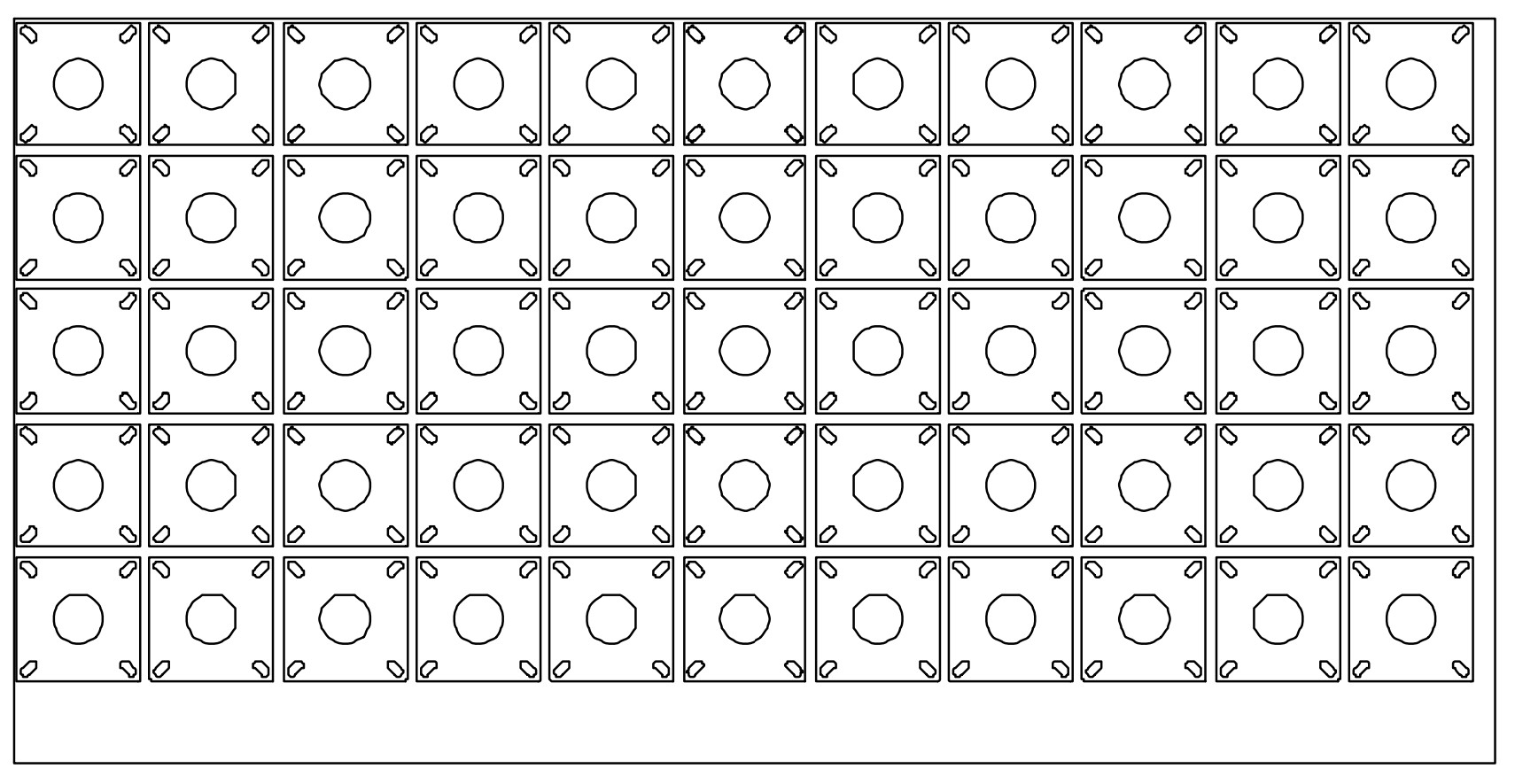
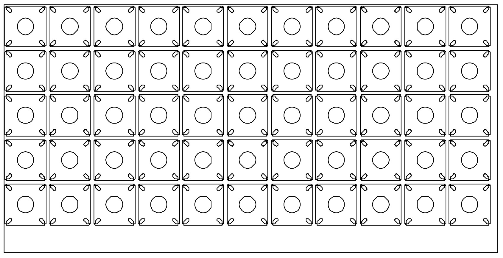
For comparison I nested both Baseplate 1 and Baseplate 2 separately on 60” x 120” plates. I used the cut settings our laser uses to cut 0.375” plate. The cut speed was set at 5.249 in/s and pierce time was set as 0.5 seconds.
Here are the numbers the nesting software calculated.
| Baseplate 1 – Individual Slots | Baseplate 2 – Continuous Cut Path | Time Saved / Time Added | |
| Laser Process Time | 22 min 37.7 s | 16 min 20.5 s | 6 min 17.2 s |
| Laser Pierce Time | 2 min 42.7 s (330 total pierces) | 54.2 s (110 total pierces) | 1 min 48.5 s |
| Laser Cut Time | 13 min 9.5 s | 13 min 28.3 s | 18.7 s |
| Laser Move Time | 6 min 33.6 s | 1 min 53.8 s | 4 min 39.8 s |
This small design change resulted in a savings of 6 minutes and 17.2 seconds per plate, a significant reduction for such a simple tweak. I expected to see time savings from reducing the number of pierces, but what surprised me was that move time savings were more than double the pierce time savings. On reflection, it makes perfect sense. Between cuts, the laser head doesn’t just move laterally—it must also retract to a safe height, reposition, and lower again before the next cut. It also has to decelerate and accelerate again between segments and when cutting sharp corners. With rounded corners and a single continuous cut path, the laser transitions smoothly, minimizing slowdowns and eliminating unnecessary repositioning. The slight increase in laser cut time is well worth the overall time saved from the design change. The Baseplate 2 design improves the cutting efficiency by ~28%, which means the laser department can now cut 28% more parts in the time spent to cut Baseplate 1 design.
One final note, the above numbers are calculated based on the lasers we employ at Texas Metal Works. Our lasers are 22kW and the laser heads have a 4G 200m/min idle movement speed. We need these specifications because we cut thick plates and a bunch of holes for our welding tables on a daily basis, so our cuts need to be powerful, clean, and fast. Most companies don’t need these specifications for their lasers. The same comparison test run on less powerful lasers might see much greater time savings due to the cut optimization.
The Takeaway
Design tweaks can be a powerful, low effort way of improving manufacturing efficiencies. So if you’re trying to get more done with your existing equipment, don’t just look at operations—take another look at your designs. Although I have used this design strategy to save laser time on Texas Metal Works products, these results have definitely pushed me to review parts that look similar to the light pole baseplate. What parts are you planning on redesigning?